
Plot coordinate pairs

You are encouraged to solve this task according to the task description, using any language you may know.
Plot a function represented as `x', `y' numerical arrays.
Post link to your resulting image for input arrays (see Example section for Python language on Query Performance page):
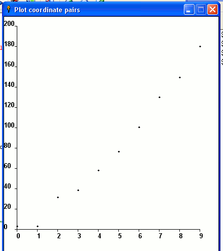
x = {0, 1, 2, 3, 4, 5, 6, 7, 8, 9};
y = {2.7, 2.8, 31.4, 38.1, 58.0, 76.2, 100.5, 130.0, 149.3, 180.0};
This task is intended as a subtask for Measure relative performance of sorting algorithms implementations.
C
We could use the suite provided by Raster graphics operations, but those functions lack a facility to draw text.
<lang c>#include <stdio.h>
- include <stdlib.h>
- include <math.h>
- include <plot.h>
- define NP 10
double x[NP] = {0, 1, 2, 3, 4, 5, 6, 7, 8, 9}; double y[NP] = {2.7, 2.8, 31.4, 38.1, 58.0, 76.2, 100.5, 130.0, 149.3, 180.0};
void minmax(double *x, double *y, double *minx, double *maxx, double *miny, double *maxy, int n) {
int i;
 *minx = *maxx = x[0];
 *miny = *maxy = y[0];
 for(i=1; i < n; i++) {
   if ( x[i] < *minx ) *minx = x[i];
   if ( x[i] > *maxx ) *maxx = x[i];
   if ( y[i] < *miny ) *miny = y[i];
   if ( y[i] > *maxy ) *maxy = y[i];
 }
}
/* likely we must play with this parameter to make the plot looks better
when using different set of data */
- define YLAB_HEIGHT_F 0.1
- define XLAB_WIDTH_F 0.2
- define XDIV (NP*1.0)
- define YDIV (NP*1.0)
- define EXTRA_W 0.01
- define EXTRA_H 0.01
- define DOTSCALE (1.0/150.0)
- define MAXLABLEN 32
- define PUSHSCALE(X,Y) pl_fscale((X),(Y))
- define POPSCALE(X,Y) pl_fscale(1.0/(X), 1.0/(Y))
- define FMOVESCALE(X,Y) pl_fmove((X)/sx, (Y)/sy)
int main() {
 int plotter, i;
 double minx, miny, maxx, maxy;
 double lx, ly;
 double xticstep, yticstep, nx, ny;
 double sx, sy;

 char labs[MAXLABLEN+1];
 plotter = pl_newpl("png", NULL, stdout, NULL);
 if ( plotter < 0 ) exit(1);
 pl_selectpl(plotter);
 if ( pl_openpl() < 0 ) exit(1);
 /* determines minx, miny, maxx, maxy */
 minmax(x, y, &minx, &maxx, &miny, &maxy, NP);
 lx = maxx - minx;
 ly = maxy - miny;
 pl_fspace(floor(minx) - XLAB_WIDTH_F * lx, floor(miny) - YLAB_HEIGHT_F * ly,
ceil(maxx) + EXTRA_W * lx, ceil(maxy) + EXTRA_H * ly);
 /* compute x,y-ticstep */
 xticstep = (ceil(maxx) - floor(minx)) / XDIV;
 yticstep = (ceil(maxy) - floor(miny)) / YDIV;
pl_flinewidth(0.25);
 /* compute scale factors to adjust aspect */
 if ( lx < ly ) {
   sx = lx/ly;
   sy = 1.0;
 } else {
   sx = 1.0;
   sy = ly/lx;
 }
pl_erase();
 /* a frame... */
 pl_fbox(floor(minx), floor(miny),
ceil(maxx), ceil(maxy));
 /* labels and "tics" */
 pl_fontname("HersheySerif");
 for(ny=floor(miny); ny < ceil(maxy); ny += yticstep) {
   pl_fline(floor(minx), ny, ceil(maxx), ny);
   snprintf(labs, MAXLABLEN, "%6.2lf", ny);
   FMOVESCALE(floor(minx) - XLAB_WIDTH_F * lx, ny);
   PUSHSCALE(sx,sy);
   pl_label(labs);
   POPSCALE(sx,sy);
 }
 for(nx=floor(minx); nx < ceil(maxx); nx += xticstep) {
   pl_fline(nx, floor(miny), nx, ceil(maxy));
   snprintf(labs, MAXLABLEN, "%6.2lf", nx);
   FMOVESCALE(nx, floor(miny));
   PUSHSCALE(sx,sy);
   pl_ftextangle(-90);
   pl_alabel('l', 'b', labs);
   POPSCALE(sx,sy);
 }
 /* plot data "point" */
 pl_fillcolorname("red");
 pl_filltype(1);
 for(i=0; i < NP; i++)
 {
   pl_fbox(x[i] - lx * DOTSCALE, y[i] - ly * DOTSCALE,
           x[i] + lx * DOTSCALE, y[i] + ly * DOTSCALE);
 }
 pl_flushpl();
 pl_closepl();
}</lang>
No one would use the previous code to produce a plot (that looks this way; instead, normally we produce data through a program, then we plot the data using e.g. gnuplot or other powerful tools; the result (with gnuplot and without enhancement) could look like this instead.
Writing EPS

Following code creates a plot in EPS format, with auto scaling and line/symbol/color controls. Plotting function loosely follows Matlab command style. Not thorough by any means, just to give an idea on how this kind of things can be coded.
<lang C>#include <stdio.h>
- include <math.h>
- include <string.h>
- define N 40
double x[N], y[N];
void minmax(double x[], int len, double *base, double *step, int *nstep) { int i; double diff, minv, maxv; *step = 1;
minv = maxv = x[0]; for (i = 1; i < len; i++) { if (minv > x[i]) minv = x[i]; if (maxv < x[i]) maxv = x[i]; } if (minv == maxv) { minv = floor(minv); maxv = ceil(maxv); if (minv == maxv) { minv--; maxv++; } } else { diff = maxv - minv; while (*step < diff) *step *= 10; while (*step > diff) *step /= 10; if (*step > diff / 2) *step /= 5; else if (*step > diff / 5) *step /= 2; }
*base = floor(minv / *step) * *step; *nstep = ceil(maxv / *step) - floor(minv / *step); }
/* writes an eps with 400 x 300 dimention, using 12 pt font */
- define CHARH 12
- define CHARW 6
- define DIMX 398
- define DIMY (300 - CHARH)
- define BOTY 20.
int plot(double x[], double y[], int len, char *spec) { int nx, ny, i; double sx, sy, x0, y0; char buf[100]; int dx, dy, lx, ly; double ofs_x, ofs_y, grid_x;
minmax(x, len, &x0, &sx, &nx); minmax(y, len, &y0, &sy, &ny);
dx = -log10(sx); dy = -log10(sy);
ly = 0; for (i = 0; i <= ny; i++) { sprintf(buf, "%g\n", y0 + i * sy); if (strlen(buf) > ly) ly = strlen(buf); } ofs_x = ly * CHARW;
printf("%%!PS-Adobe-3.0\n%%%%BoundingBox: 0 0 400 300\n" "/TimesRoman findfont %d scalefont setfont\n" "/rl{rlineto}def /l{lineto}def /s{setrgbcolor}def " "/rm{rmoveto}def /m{moveto}def /st{stroke}def\n", CHARH); for (i = 0; i <= ny; i++) { ofs_y = BOTY + (DIMY - BOTY) / ny * i; printf("0 %g m (%*.*f) show\n", ofs_y - 4, ly, dy, y0 + i * sy); if (i) printf("%g %g m 7 0 rl st\n", ofs_x, ofs_y); } printf("%g %g m %g %g l st\n", ofs_x, BOTY, ofs_x, ofs_y);
for (i = 0; i <= nx; i++) { sprintf(buf, "%g", x0 + i * sx); lx = strlen(buf); grid_x = ofs_x + (DIMX - ofs_x) / nx * i;
printf("%g %g m (%s) show\n", grid_x - CHARW * lx / 2, BOTY - 12, buf); if (i) printf("%g %g m 0 7 rl st\n", grid_x, BOTY); } printf("%g %g m %g %g l st\n", ofs_x, BOTY, grid_x, BOTY);
if (strchr(spec, 'r')) printf("1 0 0 s\n"); else if (strchr(spec, 'b')) printf("0 0 1 s\n"); else if (strchr(spec, 'g')) printf("0 1 0 s\n"); else if (strchr(spec, 'm')) printf("1 0 1 s\n");
if (strchr(spec, 'o')) printf("/o { m 0 3 rm 3 -3 rl -3 -3 rl -3 3 rl closepath st} def " ".5 setlinewidth\n");
if (strchr(spec, '-')) { for (i = 0; i < len; i++) { printf("%g %g %s ", (x[i] - x0) / (sx * nx) * (DIMX - ofs_x) + ofs_x, (y[i] - y0) / (sy * ny) * (DIMY - BOTY) + BOTY, i ? "l" : "m"); } printf("st\n"); }
if (strchr(spec, 'o')) for (i = 0; i < len; i++) { printf("%g %g o ", (x[i] - x0) / (sx * nx) * (DIMX - ofs_x) + ofs_x, (y[i] - y0) / (sy * ny) * (DIMY - BOTY) + BOTY); }
printf("showpage\n%%EOF");
return 0; }
int main() { int i; for (i = 0; i < N; i++) { x[i] = (double)i / N * 3.14159 * 6; y[i] = -1337 + (exp(x[i] / 10) + cos(x[i])) / 100; } /* string parts: any of "rgbm": color; "-": draw line; "o": draw symbol */ plot(x, y, N, "r-o"); return 0; }</lang>
gnuplot

<lang gnuplot>unset key # Only one data set, so the key is uninformative
plot '-' # '-' can be replaced with a filename, to read data from that file.
 0   2.7
 1   2.8
 2  31.4
 3  38.1
 4  68.0
 5  76.2
 6 100.5
 7 130.0
 8 149.3
 9 180.0
e</lang>
F#
Using the F# for Visualization library:

<lang fsharp>#r @"C:\Program Files\FlyingFrog\FSharpForVisualization.dll"
let x = Seq.map float [|0; 1; 2; 3; 4; 5; 6; 7; 8; 9|] let y = [|2.7; 2.8; 31.4; 38.1; 58.0; 76.2; 100.5; 130.0; 149.3; 180.0|]
open FlyingFrog.Graphics
Plot([Data(Seq.zip x y)], (0.0, 9.0))</lang>
Haskell
gnuplot is a package from HackageDB. <lang haskell>import Graphics.Gnuplot.Simple
pnts = [2.7, 2.8, 31.4, 38.1, 58.0, 76.2, 100.5, 130.0, 149.3, 180.0]
doPlot = plotPathStyle [ ( Title "plotting dots" )]
(PlotStyle Points (CustomStyle [])) (zip [0..] pnts)</lang>
HicEst
<lang HicEst>REAL :: n=10, x(n), y(n)
x = (0, 1, 2, 3, 4, 5, 6, 7, 8, 9) y = (2.7, 2.8, 31.4, 38.1, 58.0, 76.2, 100.5, 130.0, 149.3, 180.0)
WINDOW(WINdowhandle=wh, Width=-300, Height=-300, X=1, TItle='Rosetta')
AXIS(WINdowhandle=wh, Title='x values', Yaxis, Title='y values')
LINE(X=x, Y=y, SymbolDiameter=2)</lang>

J
<lang j>require 'plot' X=: i.10 Y=: 2.7 2.8 31.4 38.1 58.0 76.2 100.5 130.0 149.3 180.0 'dot; pensize 2.4' plot X;Y</lang> Output of plot.
Java
 import java.awt.*;
 import java.awt.event.*;
 import java.awt.geom.*;
 import javax.swing.JApplet;
 import javax.swing.JFrame;
 public class Plot2d extends JApplet {
   double[] xi;
   double[] yi;
   public Plot2d(double[] x, double[] y) {
       this.xi = x;
       this.yi = y;
   }
   public static double max(double[] t) {
       double maximum = t[0];
       for (int i = 1; i < t.length; i++) {
           if (t[i] > maximum) {
               maximum = t[i];
           }
       }
       return maximum;
   }
   public static double min(double[] t) {
       double minimum = t[0];
       for (int i = 1; i < t.length; i++) {
           if (t[i] < minimum) {
               minimum = t[i];
           }
       }
       return minimum;
   }
   public void init() {
       setBackground(Color.white);
       setForeground(Color.white);
   }
   public void paint(Graphics g) {
       Graphics2D g2 = (Graphics2D) g;
       g2.setRenderingHint(RenderingHints.KEY_ANTIALIASING,
               RenderingHints.VALUE_ANTIALIAS_ON);
       g2.setPaint(Color.black);
       int x0 = 70;
       int y0 = 10;
       int xm = 670;
       int ym = 410;
       int xspan = xm - x0;
       int yspan = ym - y0;
       double xmax = max(xi);
       double xmin = min(xi);
       double ymax = max(yi);
       double ymin = min(yi);
       g2.draw(new Line2D.Double(x0, ym, xm, ym));
       g2.draw(new Line2D.Double(x0, ym, x0, y0));
       for (int j = 0; j < 5; j++) {
           int interv = 4;
           g2.drawString("" + (j * (xmax - xmin) / interv + xmin), j * xspan / interv + x0 - 10, ym + 20);
           g2.drawString("" + (j * (ymax - ymin) / interv + ymin), x0 - 20 - (int) (9 * Math.log10(ymax)),
ym - j * yspan / interv + y0 - 5);
           g2.draw(new Line2D.Double(j * xspan / interv + x0, ym, j * xspan / interv + x0, ym + 5));
           g2.draw(new Line2D.Double(x0 - 5, j * yspan / interv + y0, x0, j * yspan / interv + y0));
       }
       for (int i = 0; i < xi.length; i++) {
           int f = (int) ((xi[i] - xmin) * xspan / (xmax - xmin));
           int h = (int) (((ymax - ymin) - (yi[i] - ymin)) * yspan / (ymax - ymin));
           g2.drawString("o", x0 + f - 3, h + 14);
       }
       for (int i = 0; i < xi.length - 1; i++) {
           int f = (int) ((xi[i] - xmin) * xspan / (xmax - xmin));
           int f2 = (int) ((xi[i + 1] - xmin) * xspan / (xmax - xmin));
           int h = (int) (((ymax - ymin) - (yi[i] - ymin)) * yspan / (ymax - ymin));
           int h2 = (int) (((ymax - ymin) - (yi[i + 1] - ymin)) * yspan / (ymax - ymin));
           g2.draw(new Line2D.Double(f + x0, h + y0, f2 + x0, h2 + y0));
       }
   }
   public static void main(String args[]) {
       JFrame f = new JFrame("ShapesDemo2D");
       f.addWindowListener(new WindowAdapter() {
           public void windowClosing(WindowEvent e) {
               System.exit(0);
           }
       });
       double[] r = {0, 1, 2, 3, 4, 5, 6, 7, 8, 9};
       double[] t = {2.7, 2.8, 31.4, 38.1, 58.0, 76.2, 100.5, 130.0, 149.3, 180.09};
       JApplet applet = new Plot2d(r, t);
       f.getContentPane().add("Center", applet);
       applet.init();
       f.pack();
       f.setSize(new Dimension(720, 480));
       f.show();
   }
 }
Liberty BASIC
First version writes directly to LB's console window. <lang lb>
'Plotting coordinate pairs MainWin - Style
For i = 0 To 9
x(i) = i
Next i
y(0) = 2.7 y(1) = 2.8 y(2) = 31.4 y(3) = 38.1 y(4) = 58.0 y(5) = 76.2 y(6) = 100.5 y(7) = 130.0 y(8) = 149.3 y(9) = 180.0
Locate 4, 22 For i = 0 To 9
   Locate ((i * 4) + 2), 22
   Print i
Next i
For i = 0 To 20 Step 2
   Locate 0, (21 - i)
   Print (i * 10)
Next i
For i = 0 To 9
   Locate (x(i) * 4) + 2, (21 - (y(i)/ 10))
   Print "."
Next i
End </lang> The second version uses the more typical graphic window approach, and is written to enable easy adaptation to other data sets. <lang lb> nomainwin
DATA 0, 1, 2, 3, 4, 5, 6, 7, 8, 9 DATA 2.7, 2.8, 31.4, 38.1, 58.0, 76.2, 100.5, 130.0, 149.3, 180.0
For i = 0 To 9
READ tmp: x( i) = tmp
Next i
For i = 0 To 9
READ tmp: y( i) = tmp
Next i
'Plotting coordinate pairs WindowHeight = 500 WindowWidth = 430 Open "Plot coordinate pairs" For Graphics_nsb_nf As #gwin
- gwin "trapclose [quit.gwin]"
- gwin "Color Black; Down"
'25, 418 is 0,0 global offsetX, offsetY, scaleX, scaleY offsetX = 25: offsetY = 418 scaleX = 40: scaleY = 2 maxX = 9: maxY = 200
- gwin "line "; sx( maxX);" "; sy( 0);" "; sx( 0); " "; sy( 0)
- gwin "goto "; sx( 0); " "; sy( maxY)
For x = 0 To 9
   #gwin "place ";sx(x);" ";sy(0)
   #gwin "Go -18"
   #gwin "|"; x
Next
- gwin "turn 90"
For y = 0 To 200 Step 20
   #gwin "place ";sx(0);" ";sy(y)
   #gwin "Go -5"
   #gwin "place ";0;" ";sy(y)
   #gwin "|"; y
Next
- gwin "size 3"
For i = 0 To 9
#gwin "set ";sx(x(i));" ";sy(y(i))
Next i
- gwin "Flush"
Wait
[quit.gwin]
   Close #gwin
   End
'x, y to screen x, y function sx(x)
sx = offsetX +x*scaleX
end function
function sy(y)
sy = offsetY-y*scaleY 'y is inverted
end function </lang> LB screen
Mathematica
<lang Mathematica>x={0,1,2,3,4,5,6,7,8,9}; y={2.7,2.8,31.4,38.1,58.0,76.2,100.5,130.0,149.3,180.0}; ListPlot[{x, y} // Transpose]</lang> Output: [1]
MATLAB
<lang MATLAB>>> x = [0, 1, 2, 3, 4, 5, 6, 7, 8, 9]; >> y = [2.7, 2.8, 31.4, 38.1, 58.0, 76.2, 100.5, 130.0, 149.3, 180.0]; >> plot(x,y,'.-')</lang>
Maxima
<lang maxima>(%i1) ".." (m, n) := makelist (i, i, m, n); infix ("..")$ (%i2) x: 0 .. 9$ y:[2.7, 2.8, 31.4, 38.1, 58.0, 76.2, 100.5, 130.0, 149.3, 180.0]$ (%i3) plot2d(['discrete, x, y], [style, [points,5,1,1]], [gnuplot_term, png], [gnuplot_out_file, "qsort-range-10-9.png"])$</lang>
OCaml
<lang ocaml>#load "graphics.cma" open Graphics
let round x = int_of_float (floor(x +. 0.5))
let x = [0; 1; 2; 3; 4; 5; 6; 7; 8; 9] and y = [2.7; 2.8; 31.4; 38.1; 58.0; 76.2; 100.5; 130.0; 149.3; 180.0]
let () =
 open_graph "";
 List.iter2
   (fun x y ->
     (* scale to fit in the window *)
     let _x = x * 30
     and _y = round(y *. 2.0) in
     plot _x _y)
   x y;
 ignore(wait_next_event [Key_pressed]);
 close_graph();
- </lang>
Using the Archimedes library, one can write:

<lang ocaml> module A = Archimedes
let y = [|2.7; 2.8; 31.4; 38.1; 58.0; 76.2; 100.5; 130.0; 149.3; 180.0|]
let () =
 let vp = A.init [] in
 A.Axes.box vp;
 A.set_color vp A.Color.red;
 A.Array.y vp y;
 A.close vp
</lang>
Octave
<lang octave>x = [0, 1, 2, 3, 4, 5, 6, 7, 8, 9]; y = [2.7, 2.8, 31.4, 38.1, 58.0, 76.2, 100.5, 130.0, 149.3, 180.0]; plot(x,y,"o"); pause;</lang>
PARI/GP
<lang parigp>plothraw(vx, vy)</lang>
Perl
<lang perl>use GD::Graph::points;
@data = (
 [0, 1, 2, 3, 4, 5, 6, 7, 8, 9],
 [2.7, 2.8, 31.4, 38.1, 58.0, 76.2, 100.5, 130.0, 149.3, 180.0],
); $graph = GD::Graph::points->new(400, 300); $gd = $graph->plot(\@data) or die $graph->error;
- Save as image.
$format = $graph->export_format; open(OUF, ">qsort-range-10-9.$format"); binmode OUF; print OUF $gd->$format(); close(OUF);</lang>
<lang perl>use Imager; use Imager::Plot;
@x = (0, 1, 2, 3, 4, 5, 6, 7, 8, 9); @y = (2.7, 2.8, 31.4, 38.1, 58.0, 76.2, 100.5, 130.0, 149.3, 180.0); $plot = Imager::Plot->new(
 Width => 400,
 Height => 300,
 GlobalFont => 'PATH_TO_TTF_FONT',
); $plot->AddDataSet(
 X => \@x,
 Y => \@y,
 style => {
   marker => {
     size => 2,
     symbol => 'circle',
     color => Imager::Color->new('red'),
   },
 },
); $img = Imager->new(
 xsize => 500,
 ysize => 400,
); $img->box(filled => 1, color => 'white'); $plot->Render(Image => $img, Xoff => 50, Yoff => 350); $img->write(file => 'qsort-range-10-9.png');</lang>
Perl 6
Generate an SVG image file. <lang perl6>use SVG; use SVG::Plot;
my @x = (0, 1, 2, 3, 4, 5, 6, 7, 8, 9); my @y = (2.7, 2.8, 31.4, 38.1, 58.0, 76.2, 100.5, 130.0, 149.3, 180.0);
my $svg = SVG::Plot.new(
   width       => 512,
   height      => 512,
   x           => @x,
   x-tick-step => { 1 },
   values      => [@y],
   title  => 'Coordinate Pairs',
).plot(:xy-lines);
say SVG.serialize($svg);</lang>

PicoLisp

<lang PicoLisp>(load "@lib/ps.l")
(scl 1)
(de plot (PsFile DX DY Lst)
  (let (SX (length Lst)  SY (apply max Lst)  N 0 Val)
     (out PsFile
        (psHead (+ DX 20) (+ DY 40))
        (font (9 . "Helvetica"))
        (if (or (=0 SX) (=0 SY))
           (window 60 12 DX DY
              (font 24 ,"Not enough Data") )
           (setq Lst  # Build coordinates
              (let X -1
                 (mapcar
                    '((Y)
                       (cons
                          (*/ (inc 'X) DX SX)
                          (- DY (*/ Y DY SY)) ) )
                    Lst ) ) )
           (color 55 95 55  # Background color
              (let (X (+ DX 40) Y (+ DY 40))
                 (poly T  0 0  X 0  X Y  0 Y  0 0) ) )
           (window 20 20 DX DY  # Plot coordinates
              (poly NIL 0 0  0 DY  (- DX 20) DY)
              (color 76 24 24
                 (poly NIL (caar Lst) (cdar Lst) (cdr Lst)) ) )
           (window 4 4 60 12 (ps (format SY *Scl)))
           (for X SX
              (window (+ 6 (*/ (dec X) DX SX)) (+ 24 DY) 30 12
                 (ps (format (dec X)) 0) ) ) )
        (page) ) ) )
(plot "plot.ps" 300 200 (2.7 2.8 31.4 38.1 58.0 76.2 100.5 130.0 149.3 180.0)) (call 'display "plot.ps")</lang>
PostScript
<lang PostScript> /x [0 1 2 3 4 5 6 7 8 9] def /y [2.7 2.8 31.4 38.1 58.0 76.2 100.5 130.0 149.3 180.0] def /i 1 def
newpath x 0 get y 0 get moveto x length 1 sub{ x i get y i get lineto /i i 1 add def }repeat stroke </lang>
PureBasic
<lang PureBasic>Structure PlotData
 x.i
 y.f
EndStructure
Global i, x, y.f, max_x, max_y, min_x = #MAXLONG, min_y = Infinity() Define count = (?serie_y - ?serie_x) / SizeOf(Integer) - 1 Global Dim MyData.PlotData(count)
Restore serie_x For i = 0 To count
 Read.i x
 MyData(i)\x = x
 If x > max_x: max_x = x:  EndIf
 If x < min_x: min_x = x:  EndIf
Next Restore serie_y For i = 0 To count
 Read.f  y
 MyData(i)\y = y
 If y > max_y: max_y = y:  EndIf
 If y < min_y: min_y = y:  EndIf
Next
Procedure UpdatePlot(Win, w, h)
 Static gblm = 20, gtrm = 5 ;graph's bottom-left and top-right margin

 Protected count = ArraySize(MyData())
 If w > gblm And h > gblm And count > 0
   SetWindowTitle(Win, "PureBasic Plot " + Str(w) + "x" + Str(h))
   Protected gw = w - gblm, gh = h - gblm ;graph's width and height
   Protected i, yf.f, xf.f
   yf = (gh - gtrm) / max_y
   xf = (gw - gtrm) / max_x

   CreateImage(0, w, h)
   Protected OutputID = ImageOutput(0)
   StartDrawing(OutputID)
     DrawingMode(#PB_2DDrawing_Transparent)
     ;- Draw grid
     For i = 0 To count
       y = gh - max_y * i / count * yf
       LineXY(gblm, y, w - gtrm, y, $467E3E)
       ; Y-scale
       DrawText(1, y - 5, RSet(StrD(i / count * max_y, 1), 5))
       x = gblm + max_x * i / count * xf
       y = gh
       ; X-Scale
       LineXY(x, y, x, gtrm, $467E3E)
       If i: DrawText(x - 5, y + 2, Str(i)): EndIf
     Next

     ;- Draw curve
     Protected ox = gblm, oy = gh, x, y
     For i = 0 To count
       x = gblm + MyData(i)\x * xf
       y = gh - MyData(i)\y * yf
       LineXY(ox, oy, x, y, $0133EE)
       ox = x: oy = y
     Next
   StopDrawing()
   ImageGadget(0, 0, 0, w, h, ImageID(0))
 EndIf
EndProcedure
Define Win = OpenWindow(#PB_Any, 0, 0, 600, 400,"", #PB_Window_SystemMenu | #PB_Window_SizeGadget) If Win
 SmartWindowRefresh(Win, 1)
 UpdatePlot(Win, WindowWidth(Win), WindowHeight(Win))
 Repeat
   Define event = WaitWindowEvent()
   Select event
     Case #PB_Event_SizeWindow
       UpdatePlot(Win, WindowWidth(Win), WindowHeight(Win))
   EndSelect
 Until event = #PB_Event_CloseWindow

 ; Save the plot if the user wants to
 If MessageRequester("Question", "Save it?", #PB_MessageRequester_YesNo) = #PB_MessageRequester_Yes
   Define File$=SaveFileRequester("Save as", "PB.png", "PNG (*.png)|*.png", 0)
   UsePNGImageEncoder()
   SaveImage(0, File$, #PB_ImagePlugin_PNG)
 EndIf
EndIf
DataSection
 serie_x: Data.i 0, 1, 2, 3, 4, 5, 6, 7, 8, 9
 serie_y: Data.f 2.7, 2.8, 31.4, 38.1, 58.0, 76.2, 100.5, 130.0, 149.3, 180.0
EndDataSection</lang>

Python

<lang python>>>> x = [0, 1, 2, 3, 4, 5, 6, 7, 8, 9] >>> y = [2.7, 2.8, 31.4, 38.1, 58.0, 76.2, 100.5, 130.0, 149.3, 180.0]
>>> import pylab >>> pylab.plot(x, y, 'bo') >>> pylab.savefig('qsort-range-10-9.png')</lang>
R
R has several different plotting paradigms. First we define the data. <lang R>x <- c(0, 1, 2, 3, 4, 5, 6, 7, 8, 9) y <- c(2.7, 2.8, 31.4, 38.1, 58.0, 76.2, 100.5, 130.0, 149.3, 180.0)</lang>
Base graphics
<lang R>plot(x,y)</lang>
Lattice/grid graphics
<lang R>library(lattice) xyplot(y~x)</lang>
Grammar of graphics
<lang R>library(ggplot2) qplot(x,y)</lang>
Tcl
This solution does not use existing plotting packages, but constructs the graphics from bare-metal Tk code. <lang Tcl>package require Tk
- The actual plotting engine
proc plotxy {canvas xs ys} {
   global xfac yfac
   set maxx [tcl::mathfunc::max {*}$xs]
   set maxy [tcl::mathfunc::max {*}$ys]
   set xfac [expr {[winfo width $canvas] * 0.8/$maxx}]
   set yfac [expr {[winfo height $canvas] * 0.8/$maxy}]
   scale $canvas x 0 $maxx $xfac
   scale $canvas y 0 $maxy $yfac
   foreach x $xs y $ys {
       dot $canvas [expr {$x*$xfac}] [expr {$y*$yfac}] -fill red
   }
}
- Rescales the contents of the given canvas
proc scale {canvas direction from to fac} {
   set f [expr {$from*$fac}]
   set t [expr {$to*$fac}]
   switch -- $direction {
       x {
           set f [expr {$from * $fac}]
           set t [expr {$to * $fac}]
           $canvas create line $f 0 $t 0
           $canvas create text $f 0 -anchor nw -text $from
           $canvas create text $t 0 -anchor n -text $to

       }
       y {
           set f [expr {$from * -$fac}]
           set t [expr {$to * -$fac}]
           $canvas create line 0 $f 0 $t
           $canvas create text 0 $f -anchor se -text $from
           $canvas create text 0 $t -anchor e -text $to
       }
   }
}
- Helper to make points, which are otherwise not a native item type
proc dot {canvas x y args} {
   set id [$canvas create oval [expr {$x-3}] [expr {-$y-3}] \
               [expr {$x+3}] [expr {-$y+3}]]
   $canvas itemconfigure $id {*}$args
}
pack [canvas .c -background white] update set xs {0 1 2 3 4 5 6 7 8 9} set ys {2.7 2.8 31.4 38.1 58.0 76.2 100.5 130.0 149.3 180.0} plotxy .c $xs $ys .c config -scrollregion [.c bbox all] .c move all 20 20
- Save image (this is the only part that requires an external library)
package require Img set im [image create photo -data .c] $im write plotxy.png -format PNG</lang> Of course, if we were generating an encapsulated postscript version, we would be able to do that directly.
Note also that in Tk 8.6, there is no need for an external library to write PNG images; the capability is directly supported.
TI-89 BASIC

<lang ti89b>FnOff PlotsOff NewPlot 1, 1, x, y ZoomData</lang>
Ursala
Ursala doesn't plot anything directly, but has libraries to generate LaTeX code for 2D and 3D graphics. The output file has to be run through LaTeX or included into a LaTeX document. Here's the way to do it just as a quick check (all default settings and dots connected with straight lines). <lang Ursala>#import std
- import flo
- import fit
- import plo
x = <0., 1., 2., 3., 4., 5., 6., 7., 8., 9.> y = <2.7, 2.8, 31.4, 38.1, 58.0, 76.2, 100.5, 130.0, 149.3, 180.0>
- output dot'tex' latex_document+ plot
main = visualization[curves: <curve[points: ~&p/x y]>]</lang> (output)
Here's one way you might do it if you were interested in publication quality graphics. The dots are connected with a cubic spline interpolating function sampled at 200 points, and the axes are nicely labeled.
<lang Ursala>main =
visualization[
  abscissa: axis[
     variable: 'problem size',
     hats: printf/*'%0.0f' ari10/0. 9.],
  ordinates: ~&iNC axis[
     variable: 'execution time ($\mu$s)',
     hats: printf/*'%0.1f' ari6/0. 180.],
  curves: <
     curve[
        points: ^(~&,chord_fit0@p/x y)* ari200/0. 9.,
        attributes: {'linecolor': 'lightgray'}],
     curve[
        scattered: true,
        points: ~&p/x y,
        attributes: {'linecolor': 'black'}]>]</lang>
(output)
Yorick
<lang yorick>x = [0, 1, 2, 3, 4, 5, 6, 7, 8, 9]; y = [2.7, 2.8, 31.4, 38.1, 58.0, 76.2, 100.5, 130.0, 149.3, 180.0]; window, 0; plmk, y, x; window, 1; plg, y, x, marks=0;</lang>
-

Output with plmk
-

Output with plg


![[1]](http://i43.tinypic.com/2a689yw.png)